(This mod offered by George Myers - patcoghm@sbcglobal.net)
Automatic Door Locking At Start
No wires need to be cut. I piggy backed my wires into the connectors.
** To activate:
Drivers Doors Closed.
Depress the brake.
Push the Power Button
All doors lock in the Ready mode.
** Restrictions to Operation:
Locks ONLY from Off mode.
Will not lock from IGN or ACC mode.
Locks before the car moves.
All lock features work normally.
** Parts needed:
Total cost for parts $ 34.64, with parts left over for the next project.
ICB90 PC Board, # 276-0148, Radio Shack, $1.79
2- SPDT 12V DC 1 Amp Relays, #275-0241A, Radio Shack, $4.49 X 2 = $8.98
Pack Connectors, 14-18, #85326, Pep Boys, $2.99
Heat Shrink, #278-1627, Radio Shack, $2.99
#22 Stranded Wire 3 color rolls, 278-1224, Radio Shack, $5.99
24 GA Black Wire, # NTE WT24-00-25, Sandy’s Electronics, $9.95
3-Diode 50V-1Amp/20Pk, NTE 1N4001, $1.95
** Tools:
soldering iron and solder/flux
Wire cutters
Connections are made to the system without cutting or splicing
wires. If you want to splice to the wires, that’s your choice. I attached
my wires so all the wires can be unplugged leaving the wiring in factory condition.
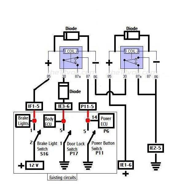
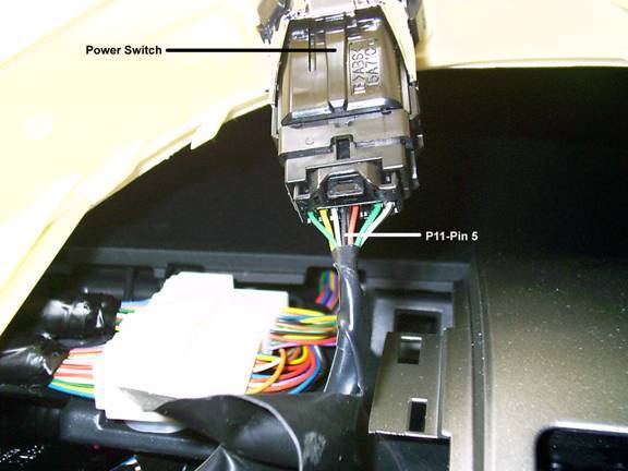
Power Button P11-pin 5, Black wire, (Ground from SS1 to Power
Control ECU)
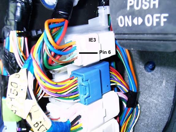
Connector IE3-pin 6, Light-green wire, (Master Door Lock)
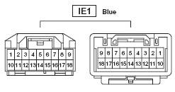
Connector IE1-pin 6, Pink, (12V Accessory)
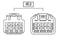
Connector IE2-pin 5. White w/ black stripe, (Ground)
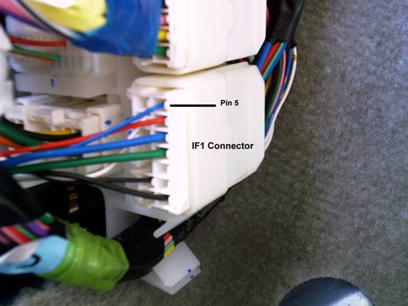
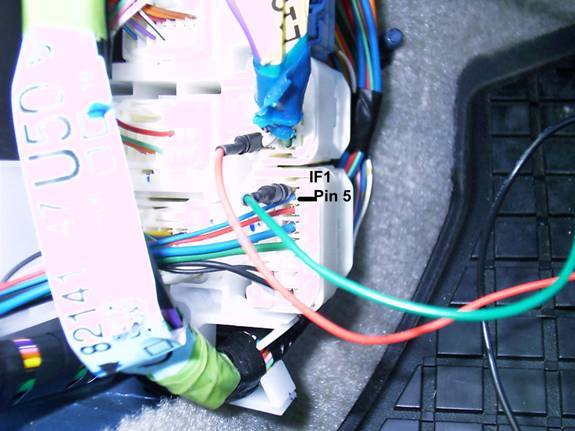
Connector IF1-pin 5, small blue wire, (Brake Light)
Plans……
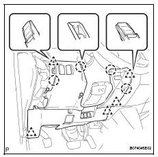
** Remove the Instrument Panel to access the Push Button Switch.
1. Remove the far left Instrument Panel register. Put your fingers
on the top edge, above the vent, and pull & pop top toward you. It really
does pop out. Then slowly pop the lower connectors.
2. Remove the lower panel, below the steering
wheel. First remove 2 screws.
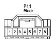
5. P-11 has 8 pin holes
Pin 1-White
Pin 2-Green
Pin 3- (Vacant)
Pin 4-Red
Pin 5-Black Connect the first wire here.
Pin 6-White/Black
Pin 7-Yellow
Pin 8-Green

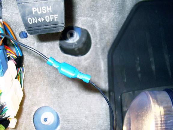
6. Cut a piece of wire long enough to go from the Push button
switch to the side cowl trim board. The side cowl trim board is located left
of the drivers side footrest.
7. Attach a connector on the wire so you can push it in the same hole with
Pin 5 (Black Wire).
8. Secure the wires together to prevent the wire from being pulled out of
the pin hole.
9. Route the other end of the wire to the side cowl trim board located left
of the driver’s side footrest.
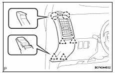
** Remove the Door Scuff Plate and Cowl Side Trim Board.
1. Remove the driver’s side door scuff plate.
2. Start at the back inside edge and pulled the lower edge inward toward the
seat, and then lifted up. It slowly pops up. The front end has a tab that
fits into a hole of the cowl side trim panel where they overlap.
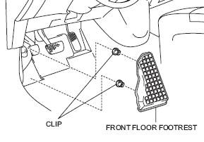
3. Remove the driver’s side footrest if more working area
is needed. (Optional)
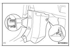
4. Remove the cowl side trim board. Pop and pull. The door edge
side pulls toward you. The rear claw is another story. The claw fastener slides
over a threaded post at the back edge near the footrest. I’m still not
sure how to remove it without breaking the small tab that presses against
the post. Thank God for “Super Glue”.
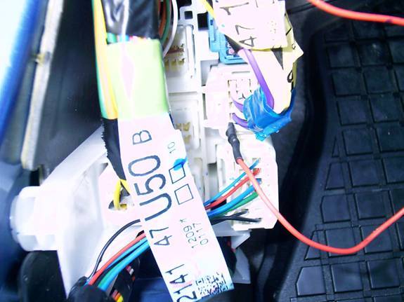
5. All the connectors are right behind the cowl side trim board.
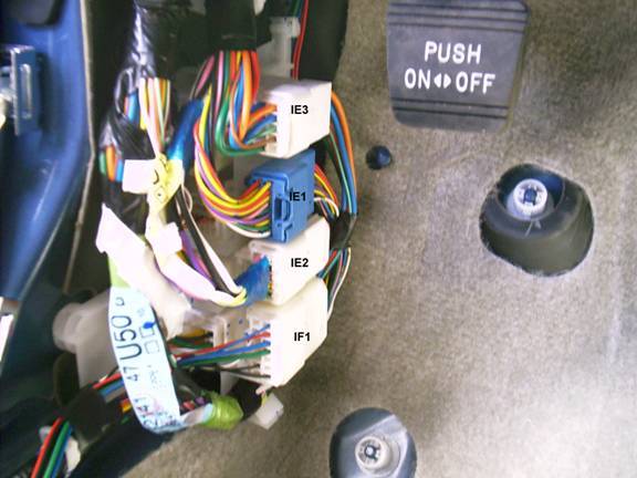
** Attach the wires to the connectors.
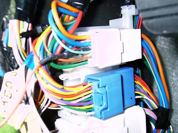
1. The connectors are from top to bottom:
IE3
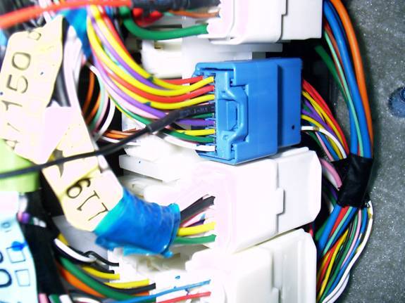
IE1, Blue connector
IE2
IF1
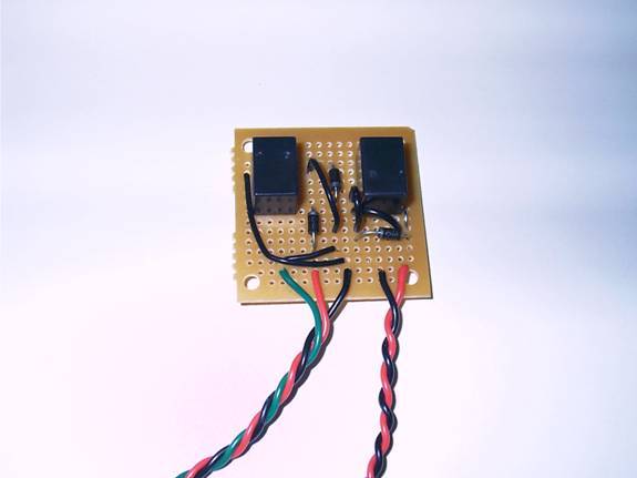
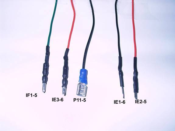
3. The Relay board has five wires, left to right are: Green,
Red, Black, Black, & Red
4. The wires attach to the connector pins as shown. Each wire
has a connector attached to fit the pin hole it connects with.
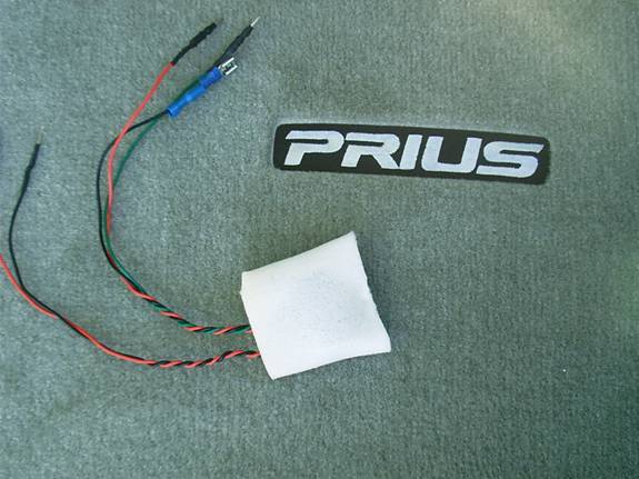
5. Insert the circuit board into a pocket made from a thin sheet
of foam. This will stop possible noise from road vibrations.
6. Attached the wires starting at the top connector to the bottom
connector.
7. Attach the 2nd wire from the left on the circuit board to
IE3-Pin 6. Insert the connector into the left side of the wire hole.
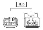
8. Attach the 4th wire from the left on the circuit board to
IE1-Pin 6. It’s the only blue connector.

9. Attach the 5th wire from the left on the circuit board to
IE2-Pin 5.

10. Attach the 1st wire from the left on the circuit board to
IF1- Pin 5.
11. Attach the 3rd wire from the left on the circuit board to
the wire from the Power Switch P11-Pin 5.
12. Check the system out.
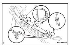
13. Secure the wires and bundle the relay board behind the wiring
harness as shown.
14. The Foam pocket fits neatly behind the wiring harness. Plastic
is on both side to insulate it, and the foam keeps it snug and rattle free.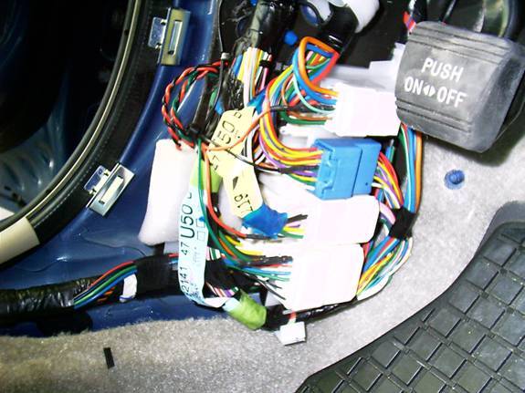
15. Install the cowl side trim board, floor footrest if removed,
and door scuff plate.
You now have automatic door locking when you start your new
Prius.