Prius - Anytime Reverse Video
Never attempt this activity. You will destroy your car and surely bring death or dismemberment upon yourself, your loved ones and your pets. I offer this information only for academic purposes, and am compelled to warn you that even veiwing it could put you in mortal danger. You assume all risk after reading beyond this line.
Wouldn't it be fun to be able to turn the reverse camera on at any time? For no *practical* reason of course... but you have to admit it would be fun! Well, it can be done! And it isn't all that hard to accomplish once you know the tricks.
With a huge debt of gratitude to PriusChat member Keydiver who worked out the wiring for this mod, I present TWO ways to accomplish the task. The first one requires the least disassembly (we'll call that the Darell way), but requires working in a tighter area, and unplugging/plugging some harnesses blindly. But NO dash disassembly is required beyond popping out the front, middle speaker in the dash (this assumes you HAVE that front middle speaker - I'm not sure the cars without the JBL factory radio do??). The second one gives you tons of room to work, and nothing is done blindly, but quite a bit of dash removal is required. I discovered the first process presented here while trying to avoid taking my dash apart yet again...
Materials:
1. Rectifier Diode, Forward Current: 1Amp Radio
Shack 1N4004 #276-1103. (2 per package, $0.89)
2. Telephone Wire Tap Connectors Radio
Shack 64-3081.
3. Small SPST toggle switch.
3. Soldering iron, solder, a few inches of 22-18 gage wire, some removable
wire-splices, shrink tube
Process 1 (less dash removal)
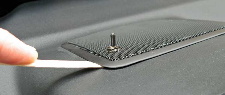
The first step is to pry out the center speaker
from the dash. I used a popcicle stick that I sharpened the flat way (like
a spatula) with a utility knife. Lift along the edge nearest you first. (ignore
the switch for now, as these pictures were taken after I was done with the
mod).
When the edge nearest you is popped up (you can
see the front two clips here, there are also two more clips, one on each side)
- just pull the whole speaker out and disconnect the white harness. The edge
toward the windshield will come out after the front is up - do NOT try to
pry the rear edge out, as those clips are different.

Now look through the windshield into the speaker
hole with a flashlight, and you'll see the two big white connectors on the
back of the MFD. Here is a picture through the windshield, and through the
speaker hole - exactly what you'll see. The speaker connector is on the left
in the foreground (red and white wires). The connector we want is the larger
white one on the driver side shown here (though we'll remove both). The clips
that hold the connectors in are on the top center of each connector. Now get
in the car, and blindly reach through the hole to find those clips, and release
both white connectors.
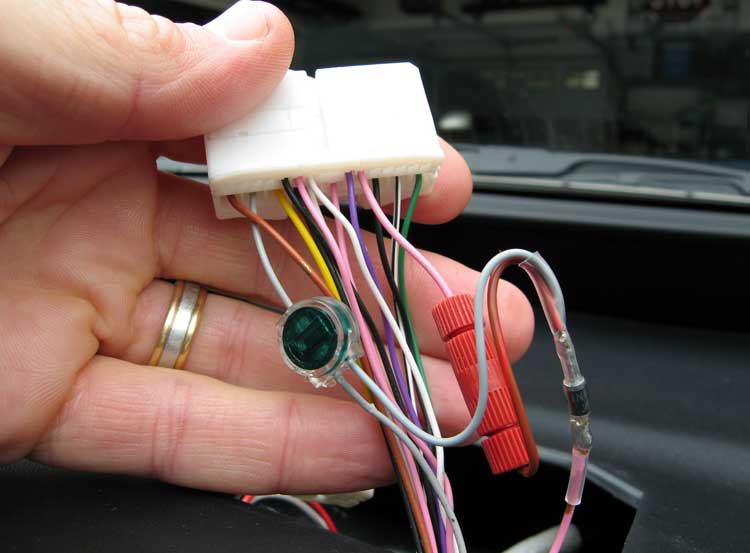
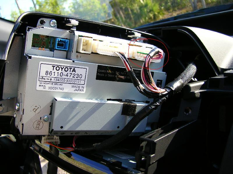
And once released, you can pull them up through
the hole. I found that releasing both of them gave me more slack, and once
you get one, the other is no problem. Shown here is the one we'll be using.
And you can see the gray and pink wire we'll use (circled in the next photo).
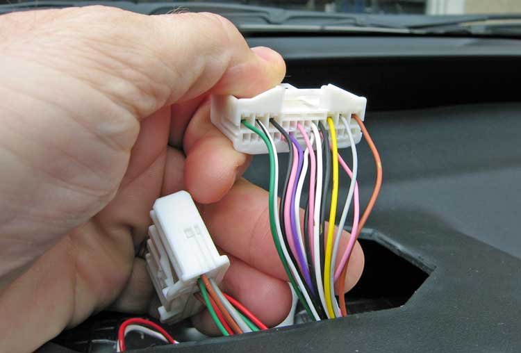
Here are the wires we'll be jumping together to
get the camera to come on. There are lots of pink ones, so make sure you get
the one next to the only purple wire.
Here are all the connections that need to be made. The goal for the switch (not shown until the next picture) is to selectively jumper the gray wire to the pink wire, and the diode is to keep the reverse lights from turning on. Nothing gets pulled to ground, we're just passing the + signal of the gray wire over to the pink wire to activate the camera and screen.
Here is the schematic (thanks to TheForce on PC)
of what we're trying to accomplish:
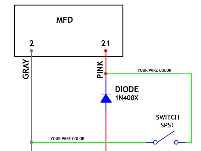
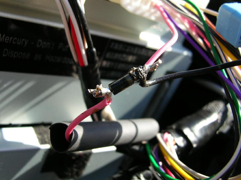
The pink wire is cut, and a diode is installed
inline (note: this can be any 1N400X series diode, like 1N4001, 1N4002, etc
from Radio Shack). The banded end of the diode is connected back to the pink
wire coming from the connector (shown here using a red wire going through
the red barrel connector) AND jumped over to the gray wire. I used a telephone
"vampire" that works great on this gage of wire. The switch will
eventually go on the added length of gray wire shown here.
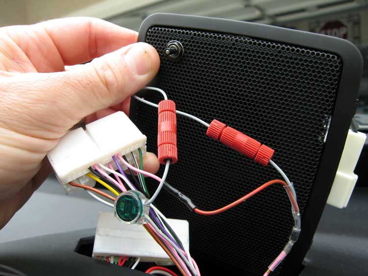
I decided to mount the toggle switch in the speaker
grill, instead of drilling into the dash somewhere. No long wire runs, and
nothing expensive gets ruined. Here I snipped the gray wire, and wired the
switch in (with barrel connectors so it is easy to again remove the speaker
without cutting wires). When mounting the switch in the grille, note the angled
shape of the speaker hole, and be sure the mount the switch so that it will
pass easily into the speaker hole.
Snap the connectors into the back of the MFD (you
do remember which one goes where, right?). Clip side up, remember! Pop the
speaker back in (some prefer the stereo sound without the middle speaker,
so you may want to try leaving the speaker harness off at this point). And
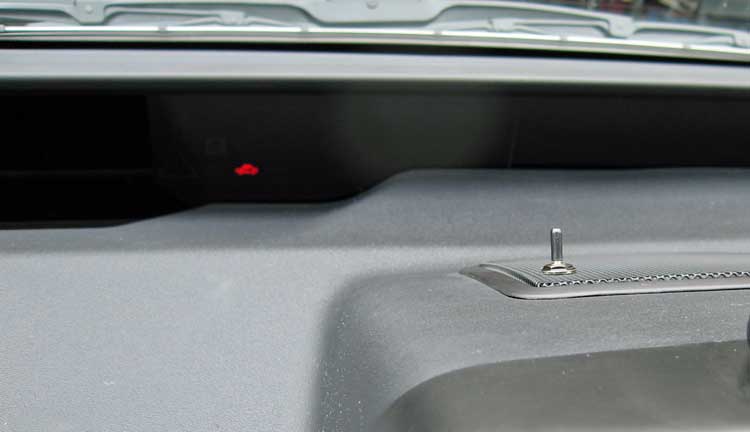
you're All done. The only outward sign that I've changed anything is this
tiny toggle switch. I painted the chrome parts of the switch black, and added
black shrink tube to the baton to make it even more unobtrusive.
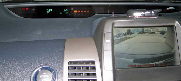
And finally, the proof that it actually works.
Notice the trans is in P, and I'm seeing down my driveway to my neighbor's
house across the street on the MFD. Success!
Process 2 (more dash removal)
1) Install a pushbutton switch in the dash, ala Evan Fusco's directions for installing the EV switch, using one of the blank plates in the dash: link A toggle switch might be more appropriate - especially if you are going to use the display for video input (DVD).
2) Follow the directions in Chris Dragon's stereo install
pdf to get the back of the MFD. link
Follow his steps carefully up to his page 7. You don't need access to the
stereo so you don't need to remove the compartment below the radio, or the
radio itself. Once you have removed the MFD, skip from page 7 to page 9 to
reinstall the panels in the proper order.
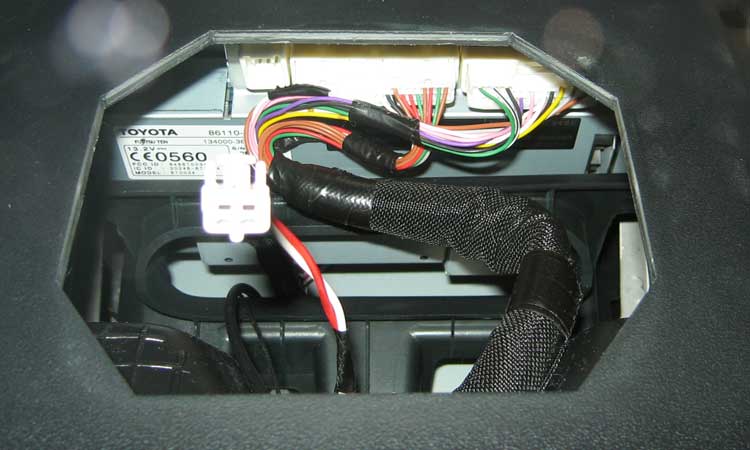
This is what the back on the MFD looks like:
The plug circled is the one that has both +12 volt power and the REVERSE wire on it. You will notice that it is the mirror image of the MFD shown on the CANVIEW site, but the power wire is the same, a gray wire on pin #2: link
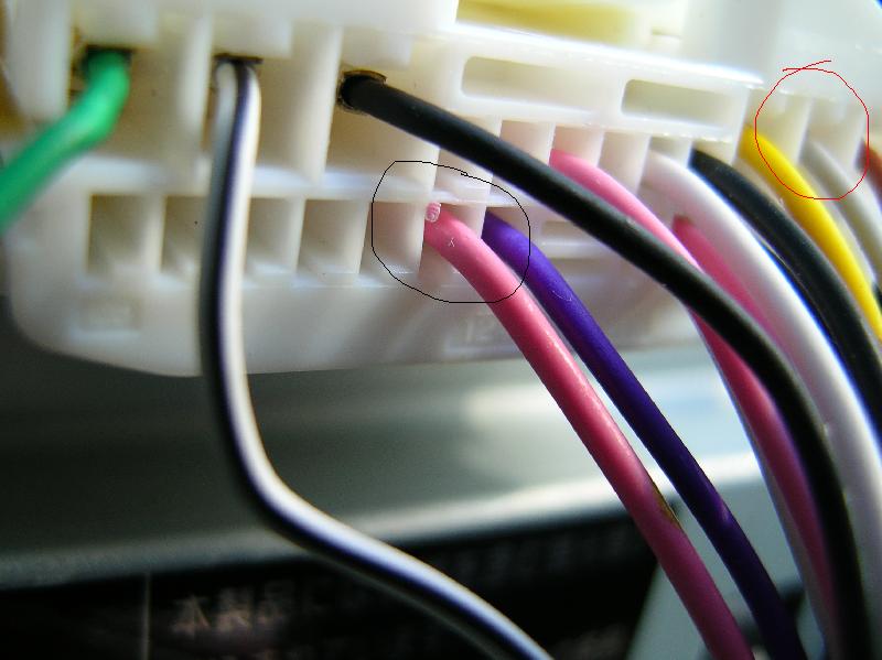
3) Here is a closer view of the 2 wires we need to tap:
The gray wire, pin #2, circled in red, is the
+12 volt power to the MFD, which we need to "vampire-clamp" to send
power to the switch.
The pink wire, pin #21, circled in black, is the reverse trigger wire from
the backup lights to the MFD. According to my schematic, on a NAV-equipped
car this is a red wire. This wire needs to be cut, and a diode installed into
it with the banded end toward the MFD, to keep our new switch from turning
on the backup lights.
4) Diode installation (note: this can be any 1N400X
series diode, like 1N4001, 1N4002, etc):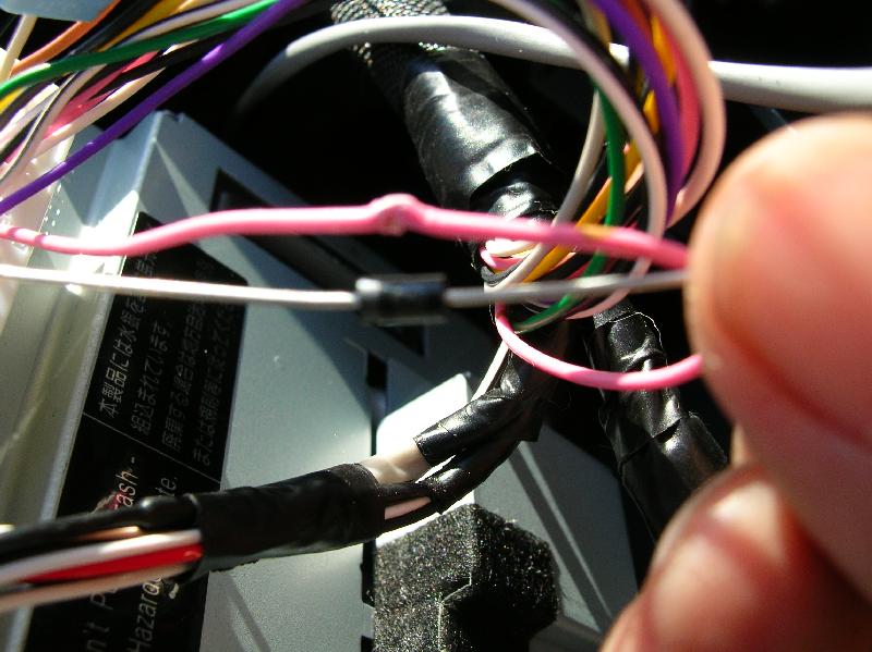
Remove the electrical tape wrapped around the
bundle to give you more wire to work with, and cut the pink wire. Slip a piece
of heat shrink onto the pink wire before soldering. Also, you will want to
solder one of the wires from your switch to the banded end of the diode, the
end connected to the MFD connector. Use a heat gun to shrink the heat shrink
onto the diode.
5) Use a "vampire-clamp" to connect
the other wire from the switch to the +12 volt gray wire on pin #2: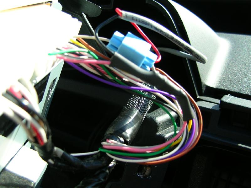
6) Follow the directions on the last page of Chris
Dragon's stereo instructions to reassemble your dash.
That's it! You can now push the button any time you want to see the rear camera.
However, as someone pointed out, it is an EXTREMELY wide angle, like a fisheye
lens, so anything more than 50-100 feet behind you is invisible.
this stuff needs to be tuned up with pictures and such. Confusing in this raw form...
The wires we're concerned with are the red and black wires on M14, the large connector on the back of the MFD. The red wire is the + video, and the black one to the left of it is actually black shrinkwrap on a bare shielded wire. Both are part of a single coaxial video cable. You just need to remove the electrical tape that's in the way, cut the red wire, loop it through the jack, and tap onto the shielded wire for a video ground
The wire is coaxial, which means that there is an insulated conductor in the center, surrounded by a copper braided outer shield. The red center conductor is the (+), and the outer shield is the (-). Toyota took some of the outer copper braided shield, pulled it together and twisted it into something that looks like a bare stranded wire, tinned it with solder, and then wrapped it in shrinktube to keep it from shorting out to anything else. You need to cut off a little bit of that shrinkwrap, to access the (-) shield, to tie the (-) conductors from the DVD or other video source to it. The camera, MFD, and DVD jack all share a common (-) video ground input. OK?
You can't just vampire clamp the (+) wires together, as you would have BOTH the camera AND the DVD video at the same time, NOT pretty! First, as I said above, you need to tie all the (-) leads together, but not cut or break them, just bind them together into a common video ground. But, here's the tough part, which I didn't take pictures of because I didn't have my camera at work when I did it: the red wire is the video (+) coming in FROM the backup camera. What we need to do is interrupt that video, and replace it with whatever it is we want to display. So, to do this, you need 2 coaxial audio/video cables, as I described above. I just used an old audio patch cord I had laying around, from an old cassette deck, and cut the plugs off of it. You tie the braided copper shields both together with the shield you revealed when you cut into the shrink wrap. I soldered them, to make a really good connection, but you may be able to improvise with those vampire clamps. The important thing is that all 3 shields are tied together in common. Now, the red wire: you need to cut it, and solder the center conductor (+) wire from one of the audio/video cables to the end of the red wire coming FROM the camera, and solder the other center conductor (+) wire to the other end of the red wire, the piece still connected to the back of the MFD.
So, now you have 2 coaxial A/V cables, routing the video signal from the camera down to wherever you are going to mount the video jack. One has the video (+) on it from the camera, and the other will take video back up to the MFD, OK?
Here's the tricky part: you need to use
a type of jack that will automatically switch OFF the backup camera video
whenever a plug is inserted into it. You could use a standard RCA phono plug,
like a DVD player's composite video is already using, but I couldn't find
an RCA phono jack locally that had the switch built into it. So, instead,
I used a 1/4" phone plug, like the old-style headphones used, except
it is only a 2-conductor, not a 3-conductor stereo plug, Then, I bought an
adapter to go from the DVD player's RCA phone plug on the end of the cable
to a 1/4" phone plug.
Then, one needs to look VERY CLOSELY at the 3 terminal connections on the
1/4" phone jack like I used. On of the solder lugs is connected to the
outer ground ring of the jack, the metal parts that include the nut and threaded
area. That's ALL the common ground, which you need to solder BOTH coaxial
shields to. That takes care of the (-) ground part of the video. But, for
the (+) part to switch properly, look at the 2 remaining solder lugs on the
jack. If you look at it carefully, and study the construction of the jack,
you will see that one lug is connected to the prong on the jack that will
touch the tip of a 1/4" plug when inserted, so you know that has to be
the (+) video output that needs to go to the input of the MFD. So, when you
plug a video source into the jack, the (-) part of the video signal comes
in on the outer ground ring around the jack, and goes up the coaxial shields
to the MFD, whereas the (+) video signal comes in on the tip of the plug,
touches the prong on the jack, and takes it up the A/V cable that is connected
to the red wire coming out of the MFD. Then, you only have one terminal left,
which is the connection that gets OPENED whenever a plug is plugged into the
jack, which is where we want our camera video (+) to come into, so solder
the remaining coaxial center conductor to that terminal.
Jeff O.
Click for |